Archive for April 2012

Static electricity

Without flowing anywhere charge carriers, specially electrons can build up on anything.  Anyone can experience this charge storage when he/she walks on a carpeted floor in winter or in a dry place where humidity is low. When charges forms on body, an excess of shortage of electrons makes your body to be charged positively of negatively. This charge formation or storage is called static electricity.

This type of electricity is called static as they don't move  like other type of electricity (AC or DC). If the carrier body or thing touches or comes across some metallic body then a discharge happens with a spark. The body or object seems to jump during the discharge. It is the static discharge which makes it happen. 

We see lightning occurring at a  stormy day or night. Lightning might occur between clouds, or between clouds and ground in the atmosphere. This lightning is nothing but a magnified version of static electric discharge. Before the lightning happens, there is a static charge in the clouds, between different clouds of parts of clouds. In the following figure cloud to cloud (A) and cloud to ground (B) static charge build ups are shown. At figure (A) when two different clouds come sufficiently close to each other then the static discharge happens and lightning occurs. In case of (B) the positive charge in the earth attracts the negative charges of cloud and then discharge happens.


The interesting thing is that, the current flow in a lightning stroke is very high. Its about several tens of thousands or hundreds of thousands, of amperes. But this huge current can't do that much damage as it lasts for only a fraction of second.

Posted in | 2 Comments

Ohm’s Law

In circuit analysis, current, voltage and resistance and their interdependence play a vital rule. The relationship among them is called Ohm's Law. It was named after the scientist who expressed it first. This law can be denoted by three formulas:


V=IR
I =V/R
R =V/I


Where V stands for voltage, I for current and R for resistance.


One have to remember only one and he/she can derive the others by simple mathematics.

Ohm's Law can be represented by a triangle, as shown in the figure. One can cover the required one to get the relationship between them.


For example, we know E and I, and wish to determine R, we have to just cover R from the picture and see what's left:


Suppose, we know E and R, and wish to determine I, we have to just cover I from the picture and see what's left:


Lastly, if you  we know I and R, and wish to determine E, we have to just cover E from the picture and see what's left:


Posted in | 1 Comment

Ideal Voltage and Current Sources

Ideal Voltage Sources


An electrical device which can generate prescribed voltage irrespective of the current supplied to other elements is called an ideal voltage source. The ability to provide constant voltage will not be harmed by any other means like heavy load. Since load always destabilizes voltage sources and at full load no source can produce prescribed voltage so ideal voltage sources are imaginary. Ideal voltage sources are not available in real world. We use this idea of Ideal voltage source to make comparison among other voltage sources. 


In summary we can say, An ideal voltage source is an electric device which maintains a constant voltage whether we change the load or not, or we can say irrespective of the current flowing throw it. The amount of the current supplied by the source depends on the circuit connected to it.


Ideal Current Sources


An electrical device which can generate prescribed current irrespective of the circuit or other elements connected to it, is called an ideal current source.To maintain a constant current the voltage in the circuit will vary. Thus it will produce arbitrary voltage across its terminals. The figure below shows symbol of ideal current sources. 


We can say: An ideal current source maintains a prescribed or constant current irrespective of the circuit connected to it. The circuit connected to the ideal current source determines the voltage generated.


Posted in , , , | Leave a comment

BRIEF HISTORY OF ELECTRICAL ENGINEERING

Electrical engineering has a evolution which was done by few people who needs to be remembered. Among them here are some. We show our gratitude to their effort and work. Hats off to them.

01. William Gilbert (1540–1603): He was an English physician. He is the founder of magnetic science and he published De Magnete in 1600.

02. Charles A. Coulomb (1736–1806): He wan a French engineer and physicist. He published the laws of electrostatics in between 1785 and 1791. Unit of charge Coulomb was named after him.

03. JamesWatt (1736–1819): He was an English inventor. He developed the steam engine. Unit of power is named after him.

04. Alessandro Volta (1745–1827): He was an Italian physicist. He discovered the electric pile. His name is used to represent the unit of electric potential and the alternate name of this quantity (voltage).

05. Hans Christian Oersted (1777–1851): He was a Danish physicist. He discovered the connection between electricity and magnetism in 1820. His name is used to represent the unit of magnetic field strength.

06. Andr´e Marie Amp`ere (1775–1836): He was a French mathematician. He was also a chemist, and physicist. The relationship between electric current and the magnetic field was first electrically quantified by him. His name is used to represent the unit of electric current.

07. Georg Simon Ohm (1789–1854): He was a German mathematician. He investigated the relationship between voltage and current and quantified the phenomenon of resistance. First results of his work were published in 1827. Unit of resistance is named after him.

08. Michael Faraday (1791–1867): He was an English experimenter. He demonstrated electromagnetic induction in 1831. Beginning of the age of electric power was marked by his electrical transformer and electromagnetic generator. Unit of capacitance was named after him.

09. Joseph Henry (1797–1878): He was an American physicist. He discovered self-induction at around 1831. Unit of inductance was named after him. Essential structure of the telegraph was first recognized by him. Later on Samuel F. B. Morse perfected it.

10. Carl Friedrich Gauss (1777–1855): He was a German mathematician. He and Wilhelm Eduard Weber (1804–1891), a German physicist, first published the measurement of earth's magnetic field in 1833. Unit of magnetic field strength is Gauss, while unit of magnetic flux is Weber.

11. James Clerk Maxwell (1831–1879): He was a Scottish physicist. He discovered the electromagnetic theory of light. He also discovered the laws of electrodynamics. Maxwell's equations are the base of modern theory of electromagnetics.

12. ErnstWerner Siemens (1816–1892) andWilhelm Siemens (1823–1883), both were German inventors and engineers. They perfected selectrical science and contributed to the invention and development of electric machines. Their name is used to represent the modern unit of conductance.

13. Heinrich Rudolph Hertz (1857–1894): He was a German scientist and experimenter. He discovered the nature of electromagnetic waves. He then published his findings in 1888. The unit of frequency is named after him.

14. Nikola Tesla (1856–1943): He was a Croatian inventor. But in 1884 he immigrated to the United States. He invented poly-phase electric power systems. The modern AC electric power system and induction motor was his work. The unit of magnetic flux density is named after him.

Posted in | 2 Comments

Dependent (Controlled) Sources

Usually the voltage and current sources have the ability to generate specific voltage or current irrespective of any other element in the circuit. So, they are not dependent on any other circuit element and termed  as independent sources.

But the sources, whose output (current or voltage) is a function of some other voltage or current at a point in a circuit, are called dependent (or controlled) sources.

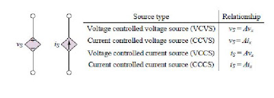
Dependent sources are represented by a symbol in the shape of a diamond. The symbol is shown in the figure. In the following table the relationship among source voltage and the dependent voltage or the source current or the dependent current is shown:


Posted in , , , | Leave a comment

Voltage and Current:

Like static electricity, electrons can be motivated to flow through a conductor. The force is the same force manifested in static electricity.

When electrons moves through a closed path then it is called a circuit. When the specific potential energy is different in two location of a circuit then electron flow from high potential to low potential. The measure of specific potential energy (potential energy per unit charge) between two locations at a circuit is called voltage. Voltage is an expression of potential energy. Hence it is always relative between two locations, or points. Most of the time it is called a voltage "drop."

 
If we connect a voltage source to a circuit, then because of the potential difference, electrons will flow uniformly through that circuit. This uniform flow of electrons is called current.


The amount of current is always same at a single loop circuit. The current will not change anywhere in the circuit. But the voltage drop will be different. 


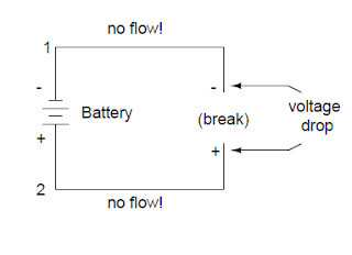
In a broken circuit, where there is a voltage source connected, then the full voltage of that source will appear across the points of the break.


The + sign shows the positive polarity in a circuit and the - sign shows the negative polarity. This convention is also relative.

Posted in , | 1 Comment

Resistance of Resistor

Resistance is the property of an electrical element which defines the measure of obstacle or how much the element will resist the flow of current. Most of the electrical elements in a circuit has some resistance. 


There are elements in a circuit which are specially made to increase the resistance of a circuit which are called resistors. Resistors resist the current to flow. Resistors are very important in circuit construction as they resist the flow of current, so they are used to allow specific amount of current at specific element as designed by the engineer.


In industry resistors are made by adding impurities in carbon. Clay to a carbon paste, or by winding a thin wire into a coil can be used as impurities.


The unit of resistance is Ohm  (Ω). The upper class Greek letter omega (Ω) is used to denote ohms. One ohm is defined as "if 1 A current is passed through a circuit having a potential difference of 1 V then the circuit has a resistance of 1 ohm".

 When there is no resistance along a path of a circuit we call it as 'short'. Short circuit can be dangerous as high current will pass through the short circuit. And if there is a high voltage source connected then short circuit can cause fire and severe damage. 


The opposite of short circuit is 'open' circuit where the path of the current is broken at any point of the circuit or network. So at an open circuit current can not flow. But the voltage will appear as it is at the two open terminal of the open circuit.  


Posted in | 2 Comments

Electric circuits:

An unbroken loop which consists of conductive material and along which electrons can flow is a circuit.


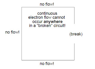
When conductive materials no longer form a complete path and continuous flow of electron is hampered then the circuit is called broken or open.

Posted in | Leave a comment

Conductors, insulators, and electron Flow

From basic chemistry, we all know that different types of atoms have different energy levels or different degrees of freedom to move around. In metals, the outer shell atoms are loosely bound and they move chaotically in between the space of the atoms. In room temperature they are so loosely bound or unbound that they can move freely and leave their respective atoms. And they can float around the space between the adjacent atoms. So they are called free electrons.

In non-metals or insulators such as glass, the electrons of the atoms are heavily bound or they have a very little freedom to move. But if external energy or force is applied such as rubbing or application of heat then the electrons are excited enough to move and leave their respective atoms and transfer to the atoms of any other material. But they do not have the ability to move between atoms within that material like metals. 

Conductivity is the measure of relative mobility of electrons within a material.


Conductivity depends on various feature of an atom. Such as, the type of the atom in a material, the atomic mass, the formation of the atoms etc. The materials which has a high mobility of electrons are called conductors. On the other hand, the materials with low electron mobility are called insulators.

Few common examples of conductors and insulators are given below:

Conductors:  silver, copper, gold, aluminum, iron, steel etc.

Insulators: glass, rubber, oil, asphalt, fiberglass, porcelain, ceramic, quartz etc.

Posted in , | 1 Comment

Conductance and the Siemens

When a substance can conduct better, we say that its resistance is less. When it conducts less, we say that its resistance is high. But most of the time electrical engineers don't mention resistance or a material rather they prefer to speak about conductance of a material.

Conductance is the ability of a substance or material to pass electricity. The measure of the opposite of resistance is conductance. Siemens, S is the unit of conductance. When a the resistance of a component is 1 ohm then its conductance is also 1 Siemens. When the resistance is increased to double, the  conductance is decreased to half and vice-versa.

The relation between Siemens and ohms can be written as:

Siemens = 1/ohms, or
ohms =1/Siemens

Posted in | 1 Comment

Transformer

Transformer: Transformer is an electrical device which transfers electrical energy through inductively coupled conductors. These inductive conductors are called coils. From Faraday's Law, we know if we give a varying current in the first or primary winding then in the core a varying magnetic flux will be induced. Thus it will induce a varying magnetic field in secondary winding. This varying magnetic field induces a varying electromotive force (EMF), or "voltage". This effect is known as inductive coupling.


Current will flow in the secondary winding, if a load is connected to it, and from the primary circuit through the transformer to the load electrical energy will be transferred . The induced voltage of an ideal transformer in the secondary winding (Vs) is in proportion to the primary voltage (Vp). It is given by the ratio which is usually called as transformer's turns ratio. The  turns ratio is ratio of the number of turns in the secondary (Ns) to the number of turns in the primary (Np) as follows:


By appropriate selection of the turns ratio, a transformer enables an alternating current (AC) voltage to be "stepped up" or "stepped down" by making Ns greater than Np, or by making Ns less than Np respectively. In most of the transformers, the windings are coils wound around a ferromagnetic core.


Transformers can be of different sizes. One can be size of a thumbnail hidden inside a stage microphone, while other can be huge units weighing hundreds of tons used to interconnect portions of power grids. But all of them operates according to the same principles. 


Now-a-days new technologies have somehow eliminated the need for transformer in some electronic circuit. But still transformers are found in almost all electronic devices which are designed for household use. Transformer are must for high voltage electric power transmission. It makes long distance transmission economical and practical.

Posted in | 10 Comments

Quiz 01: Basics of Circuit Theory


Quiz 01: Basics of Circuit Theory


Given each of the questions below, check the most appropriate response.


Please enter your name


1. What is ohms law?


R=VI


V=RV


I=V/R


I=VR


2. Which one is KCL?


Incoming current in a node = Outgoing current from that node.


Incoming voltage in a node = Outgoing voltage from that node


In a loop total sum of voltage drop = source voltage.


In a loop total sum of voltage drop = source current.


3. Nodal analysis gives =


Current at a node


Current in a loop


Voltage at a node


Voltage in a loop


4. Norton and thevenin theorem does =


Describes the currents in a loop.


Simplifies the circuit to give an equivalent resistance and source voltage or current to find load voltage or current


Has no relation with circuit theory


They gives calculation of current in a loop and voltage at a node


5. Which one is KVL?


Incoming current in a node = Outgoing current from that node.


Incoming voltage in a node = Outgoing voltage from that node


In a loop total sum of voltage drop = source voltage.


In a loop total sum of voltage drop = source current.


Copyright © 2012 Basic Electrical Engineering.


3 Comments